Vibro-Volt — Piezoelectric Energy Harvester
PVDF-based vibrational energy harvesting with interrupt-driven charge control.
- Role
- Hardware lead — analog front-end, firmware, team lead
- Timeline
- Aug 2024 – Dec 2024 (5 months)
- Team
- Led 3 engineers (analog, firmware, BMS)
- Status
- Completed
A PVDF-piezo energy harvester with interrupt-driven charge control that turns ambient vibration into usable DC for battery-powered IoT nodes — characterised in Proteus before any hardware was built, cutting iteration cycles dramatically.
Problem & motivation
Battery-powered IoT nodes deployed in vibration-rich environments still need maintenance trips to swap cells. Most of that mechanical energy goes uncaptured.
PVDF piezo elements convert mechanical vibration directly to charge. A small harvester + BMS can meaningfully extend battery life on the right kind of device — if the rectification and charge control are done carefully.
- 01Convert vibrational energy from PVDF into usable DC.
- 02Manage charge / discharge with interrupt-driven firmware.
- 03Characterise frequency response before hardware build.
- 04Lead a small team through bench → board iteration.
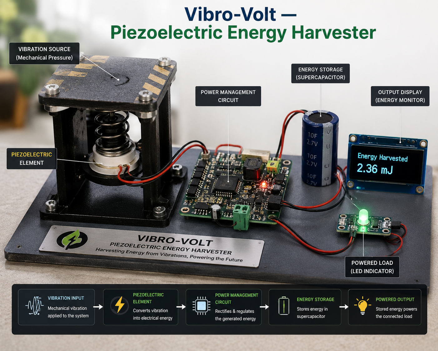
How the pieces fit together
PVDF strips feed a full-wave rectifier bridge into a storage cap and BMS. An Arduino Nano monitors voltage via ADC and drives charge / discharge state transitions on interrupt.
- Step 01PVDF piezo deflects under vibration
- Step 02Full-wave bridge rectifies AC → pulsed DC
- Step 03Smoothing cap + voltage regulator
- Step 04Arduino ADC monitors bank voltage
- Step 05Interrupt-driven state machine: harvest → charge → discharge
- Step 06Load supplied via BMS
Hardware, software & frameworks
- Arduino Nano
- PVDF piezo strips
- Schottky rectifier bridge
- Storage cap bank
- BMS
- Embedded C
- Interrupt-driven ADC sampling
- Proteus (simulation)
- Multisim
How it was built
Modeled expected vibration spectrum and back-of-envelope harvested power. Defined acceptance criteria before touching hardware.
Characterised PVDF + rectifier in Proteus across a sweep of input frequencies to pick the operating range.
Built the harvesting board, wrote the interrupt-driven ADC loop on the Arduino, and integrated the BMS.
Bench-tested with a vibration table and iterated on cap sizing until the system held a steady voltage under representative load.
What it does
- PVDF vibration energy harvesting
- Full-wave rectification + smoothing
- Interrupt-driven ADC charge control
- BMS-managed charge / discharge transitions
- Simulated frequency response before build
Problems faced & how I solved them
ADC sampling jitter caused false state transitions.
Moved sampling to a hardware timer interrupt with a small rolling-average filter; eliminated false triggers without adding latency.
Cap sizing was off in first iteration — sag under load.
Re-derived from the simulated waveform; doubled the bank and added a Schottky stage. Voltage held within spec.
What I'd take into the next build
- 01Simulating the analog front-end first is always faster than soldering twice.
- 02Interrupt-driven sampling beats polling for any energy-constrained system.
- 03Owning the team's debugging loop is as much of the work as designing the circuit.
- Move to a dedicated piezo-harvester IC (LTC3588) for production efficiency.
- Add wireless telemetry of harvested-power statistics.
Like what you see?
I'm open to embedded, IoT, and edge-AI roles — full-time, internship, or freelance.